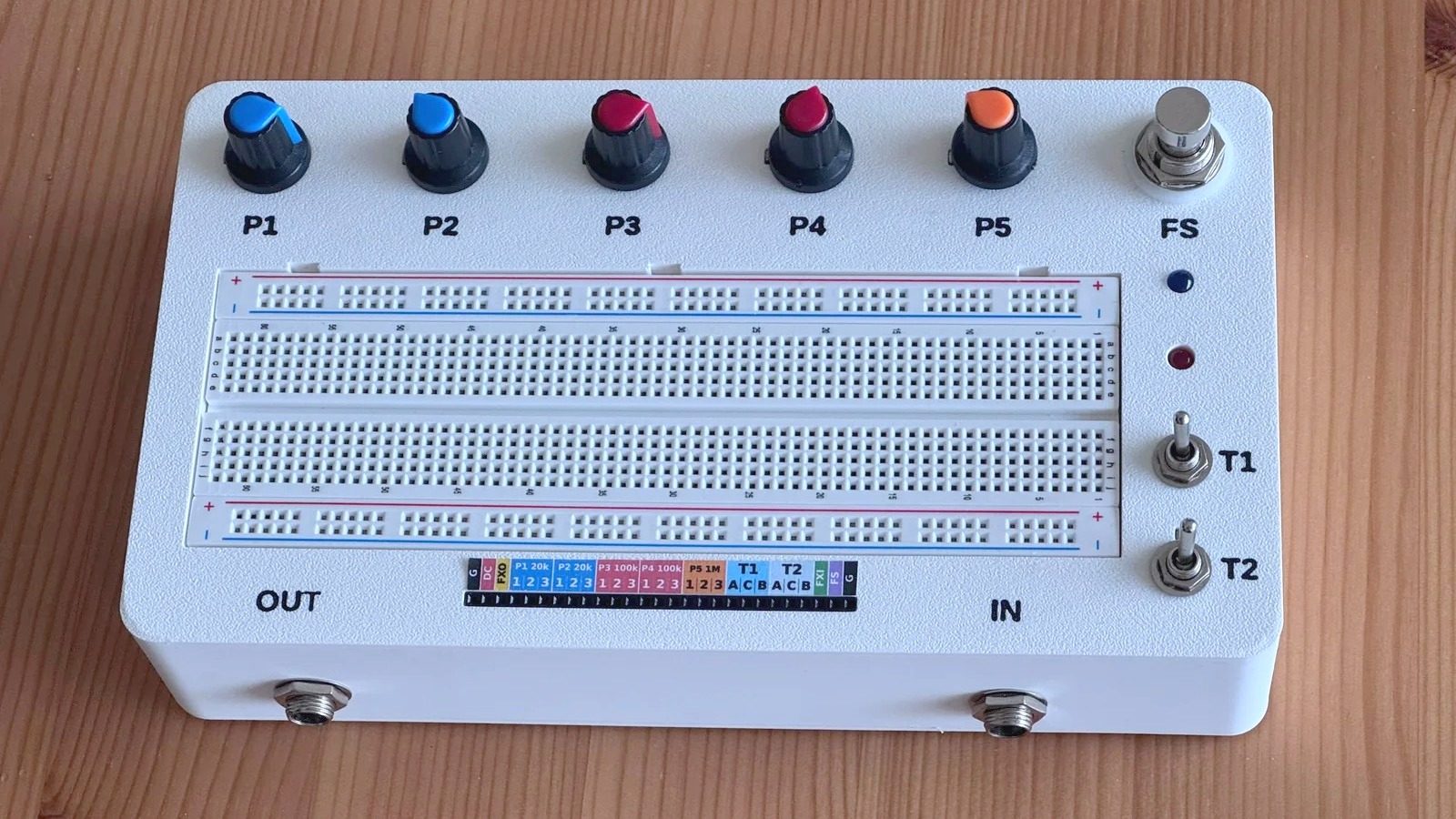
Lately I've been playing with guitar pedal circuits. The fun part is trying things: swap a capacitor, change a resistor, turn a knob and hear what happens. The not-so-fun part is everything around it.
Every circuit needs the same stuff: an input jack, an output jack, power, a footswitch, a couple of knobs. On a bare breadboard that means wires everywhere, pots flopping around on their legs, and a guitar cable pulling the whole thing off the table. And you can't really test a pedal without stepping on it.
So I made a box for it.
The idea
It's a pedal-shaped box with a breadboard sitting in a tray on top. Everything a pedal needs is already mounted and wired inside:
- 5 knobs (P1 to P5)
- 2 toggle switches
- a footswitch with true bypass
- IN and OUT jacks
- a DC power jack
- two LEDs, one for power and one that shows when the effect is on
All of it goes to one row of 27 pins right below the breadboard. So when I want to try a new circuit, I just build it on the breadboard and plug jumper wires into the pins I need. No soldering, no rewiring. When I'm done, I pull the parts out and the box is ready for the next one.
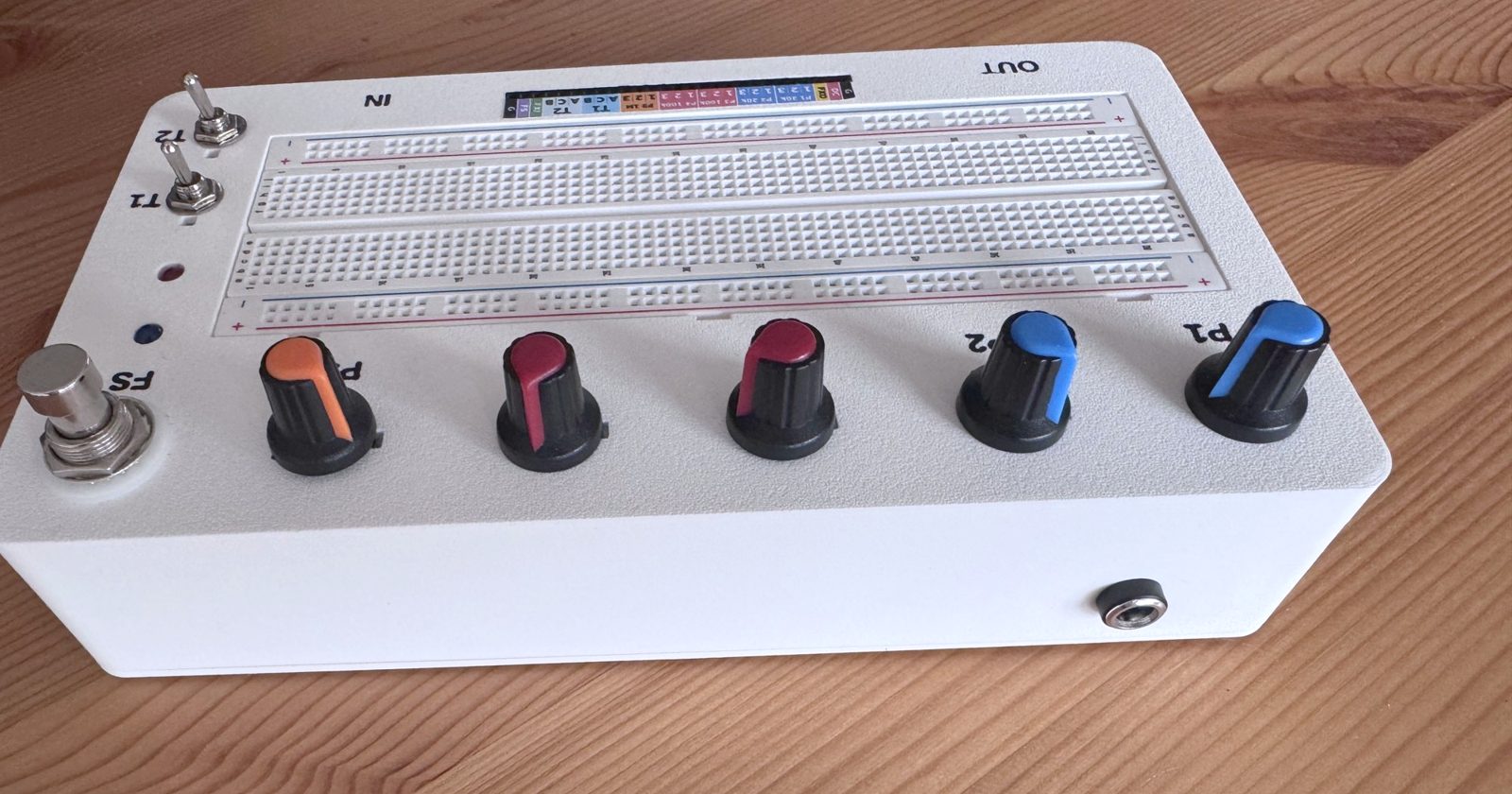
There's a little colored label next to the pins, so I don't have to remember which one is which. Each knob has its own color too, matching its value: blue for 20k, red for 100k and orange for 1M. Those are just the values I wanted to have around. If you build one, put in whatever pots you like.
Standing on a giant's box
I didn't start from zero. I found a really nice prototyping box by skngh on MakerWorld, made for the Daisy Seed, which is a small board for digital audio effects. I loved the look of it, but I wanted something for analog circuits.
So I took his box and changed a lot: made it lower, moved all the holes, added the knob and switch layout, the pin header, a new tray for the breadboard, a new lid with brass inserts, and printed labels on top. Big thanks to him for the base. It made the whole thing so much easier.
Printing it
I printed it on my Bambu Lab A1 in white PLA. The labels on top (P1, P2, FS, IN, OUT and so on) are printed in black as a second color with the AMS Lite, so they are part of the surface and won't rub off. No supports anywhere, which I was quite happy about.
It's two plates: the main body with the labels, and the lid with the tray plate. Add some brass inserts and screws, and that's the whole box.
The inside
Here's where the magic, or the spaghetti, happens:
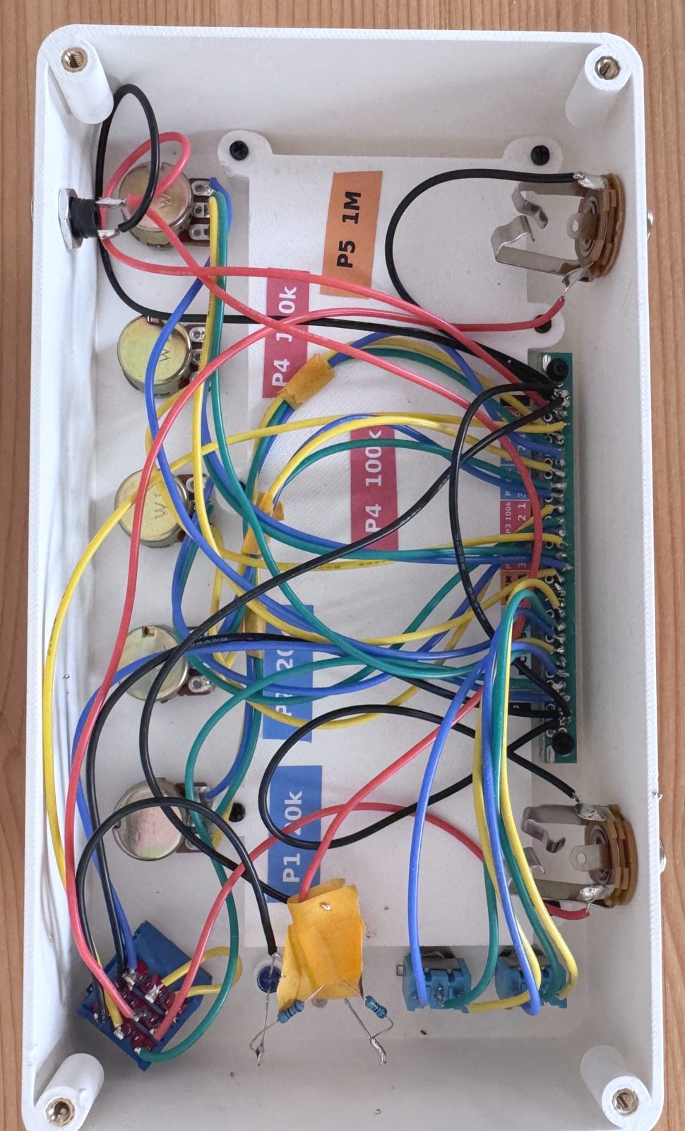
Yes, it's a bit of a jungle. But it's the kind of jungle you only build once. Each wire goes from a knob, switch or jack to its pin on the header (the green strip on the right), and after that I never have to open the box again.
One fun lesson from the first build: when I powered it up, neither LED lit. I checked everything twice. It turned out the box has two ground pins, one at each end of the header, and they needed one little wire between them. One wire, and both LEDs came on. Classic. It's now marked as a required step in the guide, so nobody else has to stare at dark LEDs.
Try it yourself
The model is on MakerWorld, with a print profile for the Bambu A1 and a PDF assembly guide that shows which wire goes where:
🔗 Guitar Pedal Prototype Breadboard on MakerWorld
Now the real fun starts: actually building pedals on it. I will share them here as I go.
If you build one, or have ideas for what to change, please let me know!
Cheers!